Node.js Raspberry Pi GPIO - Flowing LEDs
Using Array With Output to Create Flowing LEDs
In this chapter we will use several GPIO pins to create a "flowing" effect by turning them on and off in sequence.
What do we need?
For this you need:
- A Raspberry Pi with Raspian, internet, SSH, with Node.js installed
- The onoff module for Node.js
- 1 x Breadboard
- 8 x 220 Ohm resistor
- 8 x Through Hole LED
- 9 x Female to male jumper wires
Note: The resistor you need can be different from what we use depending on the type of LEDs you use. Most small LEDs only need a small resistor, around 200-500 ohms. It is generally not critical what exact value you use, but the smaller the value of the resistor, the brighter the LED will shine.
Click the links in the list above for descriptions of the different components.
Building the Circuit
Now it is time to build the circuit on our Breadboard.
If you are new to electronics, we recommend you turn off the power for the Raspberry Pi. And use an anti-static mat or a grounding strap to avoid damaging it.
Shut down the Raspberry Pi properly with the command:
pi@w3demopi:~ $ sudo shutdown -h now
After the LEDs stop blinking on the Raspberry Pi, then pull out the power plug from the Raspberry Pi (or turn of the power strip it is connected to).
Just pulling the plug without shutting down properly may cause corruption of the memory card.
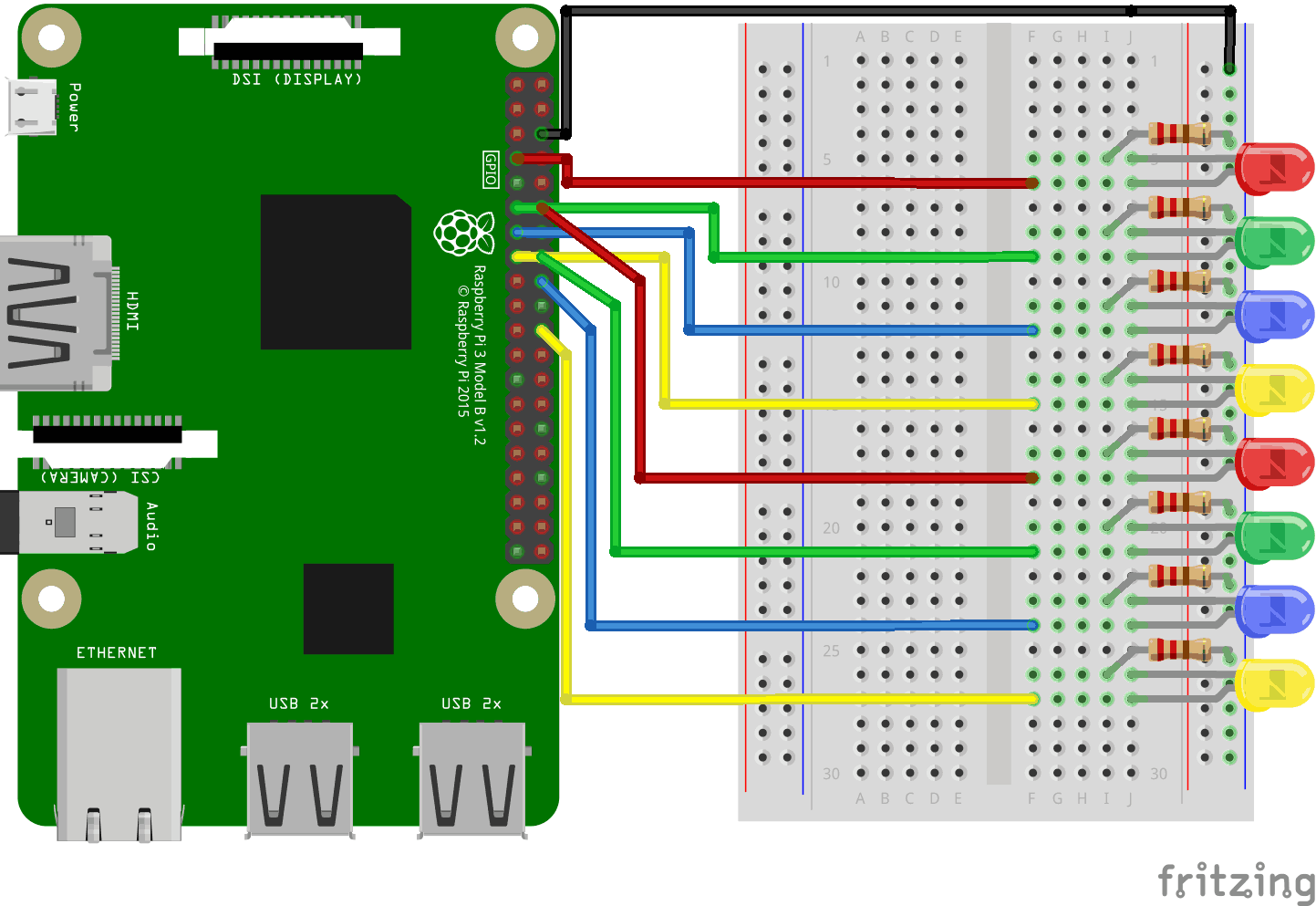
Look at the above illustration of the circuit.
- On the Raspberry Pi, connect the female leg of a jumper wire to a GND pin. In our example we used Physical Pin 6 (GND, row 3, right column)
- On the Breadboard, connect the male leg of the jumper wire connected to the GND power, to the Ground Bus on the right side. That entire column of your breadboard is connected, so it doesn't matter which row. In our example we attached it to row 1
- For each LED: Connect the LED so that it connects to 2 Tie-Point rows. In our example
we connected:
- LED1 to rows 5 (cathode) & 6 (anode) column J
- LED2 to rows 8 (cathode) & 9 (anode) column J
- LED3 to rows 11 (cathode) & 12 (anode) column J
- LED4 to rows 14 (cathode) & 15 (anode) column J
- LED5 to rows 17 (cathode) & 18 (anode) column J
- LED6 to rows 20 (cathode) & 21 (anode) column J
- LED7 to rows 23 (cathode) & 24 (anode) column J
- LED8 to rows 26 (cathode) & 27 (anode) column J
- For each LED: Connect one of the legs of a 220 ohm resistor from the the Ground Bus
column on the right side, and the other leg to the right side Tie-Point row
where it connects to the cathode leg of the LED. In our example we
connected:
- LED1 to row 5 column I
- LED2 to row 8 column I
- LED3 to row 11 column I
- LED4 to row 14 column I
- LED5 to row 17 column I
- LED6 to row 20 column I
- LED7 to row 23 column I
- LED8 to row 26 column I
- For each LED: Connect the female leg of a jumper wire to a
GPIO pin on the Raspberry Pi, and the male leg
of the jumper wire to the right side Tie-Point row
where it connects to the anode leg of the LED. In our example we connected:
- LED1 from Physical Pin 7 (GPIO 4, row 4, left column) to Tie-point row 6 column F
- LED2 from Physical Pin 11 (GPIO 17, row 6, left column) to Tie-point row 9 column F
- LED3 from Physical Pin 13 (GPIO 27, row 7, left column) to Tie-point row 12 column F
- LED4 from Physical Pin 15 (GPIO 22, row 8, left column) to Tie-point row 15 column F
- LED5 from Physical Pin 12 (GPIO 18, row 6, right column) to Tie-point row 18 column F
- LED6 from Physical Pin 16 (GPIO 23, row 8, right column) to Tie-point row 21 column F
- LED7 from Physical Pin 18 (GPIO 24, row 9, right column) to Tie-point row 24 column F
- LED8 from Physical Pin 22 (GPIO 25, row 11, right column) to Tie-point row 27 column F
Your circuit should now be complete, and your connections should look pretty similar to the illustration above.
Now it is time to boot up the Raspberry Pi, and write the Node.js script to interact with it.
Raspberry Pi and Node.js Flowing LEDs Script
Go to the "nodetest" directory, and create a new file called "flowingleds.js":
pi@w3demopi:~ $ nano
flowingleds.js
The file is now open and can be edited with the built in Nano Editor.
Write, or paste the following:
flowingleds.js
var Gpio = require('onoff').Gpio; //include onoff to interact with the GPIO
var LED04 = new Gpio(4, 'out'), //use declare variables for all the GPIO
output pins
LED17 = new Gpio(17, 'out'),
LED27 = new Gpio(27,
'out'),
LED22 = new Gpio(22, 'out'),
LED18 = new Gpio(18,
'out'),
LED23 = new Gpio(23, 'out'),
LED24 = new Gpio(24,
'out'),
LED25 = new Gpio(25, 'out');
//Put all the LED
variables in an array
var leds = [LED04,
LED17, LED27, LED22, LED18, LED23, LED24, LED25];
var indexCount = 0; //a
counter
dir = "up"; //variable for flowing direction
var
flowInterval = setInterval(flowingLeds, 100); //run the flowingLeds function
every 100ms
function flowingLeds() { //function for flowing Leds
leds.forEach(function(currentValue) { //for each item in array
currentValue.writeSync(0); //turn off LED
});
if (indexCount
== 0) dir = "up"; //set flow direction to "up" if the count reaches zero
if (indexCount >= leds.length) dir = "down"; //set flow direction to "down" if
the count reaches 7
if (dir == "down") indexCount--; //count
downwards if direction is down
leds[indexCount].writeSync(1);
//turn on LED that where array index matches count
if (dir ==
"up") indexCount++ //count upwards if direction is up
};
function unexportOnClose() {
//function to run when exiting program
clearInterval(flowInterval);
//stop flow interwal
leds.forEach(function(currentValue) { //for
each LED
currentValue.writeSync(0); //turn off LED
currentValue.unexport(); //unexport GPIO
});
};
process.on('SIGINT', unexportOnClose); //function to
run when user closes using ctrl+cc
Press "Ctrl+x" to save the code. Confirm with "y", and confirm the name with "Enter".
Run the code:
pi@w3demopi:~ $ node flowingleds.js
Now the LEDs should turn on and off in sequence, creating a flowing effect.
End the program with Ctrl+c.
