Node.js Raspberry Pi GPIO - LED and Pushbutton
Using both Input and Output
In the previous chapter we learned how to use a Raspberry Pi and its GPIO to make a LED blink.
For that we used a GPIO pin as "Output".
In this chapter we will use another GPIO pin as "Input".
Instead of blinking for 5 seconds, we want the LED to light up when you push a button connected to the breadboard.
What do we need?
In this chapter we will create a simple example where we control a LED light with a Push Button.
For this you need:
- A Raspberry Pi with Raspian, internet, SSH, with Node.js installed
- The onoff module for Node.js
- 1 x Breadboard
- 1 x 68 Ohm resistor
- 1 x 1k Ohm resistor
- 1 x Through Hole LED
- 1 x Push Button
- 4 x Female to male jumper wires
- 1 x Male to Male jumper wires
Click the links in the list above for descriptions of the different components.
Note: The resistor you need can be different from what we use depending on the type of LED you use. Most small LEDs only need a small resistor, around 200-500 ohms. It is generally not critical what exact value you use, but the smaller the value of the resistor, the brighter the LED will shine.
In this chapter we will build on the circuit we built in last chapter, so you will recognize some of the parts in the list above.
Building the Circuit
Now it is time to build the circuit on our Breadboard. We will use the circuit we created in the last chapter as a starting point.
If you are new to electronics, we recommend you turn off the power for the Raspberry Pi. And use an anti-static mat or a grounding strap to avoid damaging it.
Shut down the Raspberry Pi properly with the command:
pi@w3demopi:~ $ sudo shutdown -h now
After the LEDs stop blinking on the Raspberry Pi, then pull out the power plug from the Raspberry Pi (or turn of the power strip it is connected to).
Just pulling the plug without shutting down properly may cause corruption of the memory card.
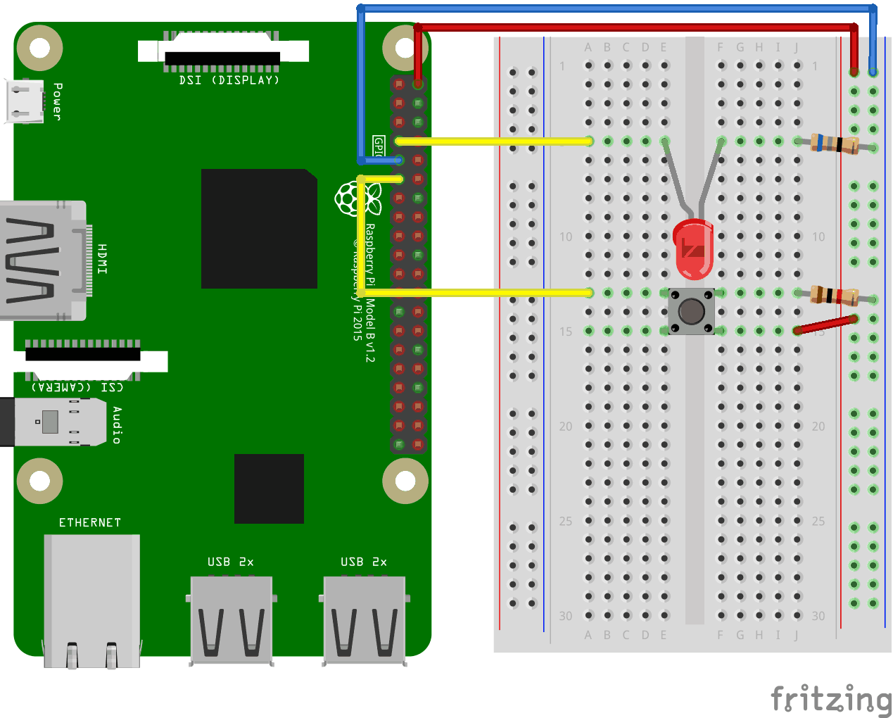
Look at the above illustration of the circuit.
- Starting with the circuit we created in the last chapter:
On the Raspberry Pi, connect the female leg of a jumper wire to a 5V power pin. In our example we used Physical Pin 2 (5V, row 1, right column) - On the Breadboard, connect the male leg of the jumper wire connected to the 5V power, to the Power Bus on the right side. That entire column of your breadboard is connected, so it doesn't matter which row. In our example we attached it to row 1
- On the Breadboard, connect the push button so that it fits across the Trench. In our example it connects to rows 13 and 15, columns E and F
- On the Breadboard, connect one leg of the 1k ohm resistor to the Ground Bus column on the right side, and the other leg to the right side Tie-Point row where it connects to one of the right side legs of the push button. In our example we attached one side to Tie-Point row 13, column J, and the other side to the closest Ground Bus hole
- On the Breadboard, connect a male-to-male jumper wire from the right Power Bus, to the right Tie-Point row that connects to the other leg of the push button. In our example we attached one side to Tie-Point row 15, column J, and the other side to the closest Power Bus hole
- On the Raspberry Pi, connect the female leg of a jumper wire to a GPIO pin. In our example we used Physical Pin 11 (GPIO 17, row 6, left column)
- On the Breadboard, connect the male leg of the jumper wire to left Tie-Point row the Push Button leg that is directly across the Ground connection leg. In our example we attached it to row 13, column A
Your circuit should now be complete, and your connections should look pretty similar to the illustration above.
Now it is time to boot up the Raspberry Pi, and write the Node.js script to interact with it.
Raspberry Pi and Node.js LED and Button Script
Go to the "nodetest" directory, and create a new file called "buttonled.js":
pi@w3demopi:~ $ nano buttonled.js
The file is now open and can be edited with the built in Nano Editor.
Write, or paste the following:
buttonled.js
var
Gpio = require('onoff').Gpio; //include onoff to interact with the GPIO
var
LED = new Gpio(4, 'out'); //use GPIO pin 4 as output
var pushButton = new
Gpio(17, 'in', 'both'); //use GPIO pin 17 as input, and 'both' button presses,
and releases should be handled
pushButton.watch(function (err, value) {
//Watch for hardware interrupts on pushButton GPIO, specify callback function
if (err) { //if an error
console.error('There was an
error', err); //output error message to console
return;
}
LED.writeSync(value); //turn LED on or off depending on the button state (0 or
1)
});
function unexportOnClose() { //function to run when exiting program
LED.writeSync(0); // Turn LED off
LED.unexport(); // Unexport LED
GPIO to free resources
pushButton.unexport(); // Unexport Button
GPIO to free resources
};
process.on('SIGINT', unexportOnClose); //function to
run when user closes using ctrl+c
Press "Ctrl+x" to save the code. Confirm with "y", and confirm the name with "Enter".
Run the code:
pi@w3demopi:~ $ node buttonled.js
Now the LED should turn on when you press the button, and turn off when you release it.
End the program with Ctrl+c.
